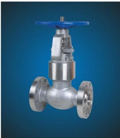
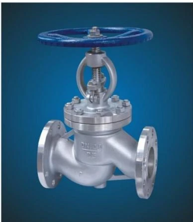
In the complex architecture of industrial piping systems, controlling the movement of fluids, gases, and steam requires more than just stopping and starting the flow. While isolation valves are perfectly suited for fully open or fully closed operations, precise volumetric regulation demands a different mechanical approach. Enter the globe valve, an indispensable cornerstone of fluid mechanics engineering designed specifically to throttle, regulate, and safely manage dynamic flow rates under varying pressure conditions.
Whether deployed in a high-pressure power plant, a petrochemical refinery, or a municipal water treatment facility, understanding the fundamental principles of the globe valve is essential for optimizing system efficiency and ensuring operational safety. This comprehensive guide explores what these valves are, how they function internally, their diverse structural variations, and the specific industrial scenarios where they excel.
What is a Globe Valve? Defining the Essentials
A globe valve is a linear-motion mechanical device utilized primarily to start, stop, and, most importantly, regulate fluid flow within a pipeline. The name "globe" originates from the traditional spherical body shape characteristic of early designs. Although modern engineering has introduced more streamlined profiles, the internal configuration retains the classic architectural logic that defines its operation.
At its core, the globe valve operates by moving a movable disc or plug relative to a stationary ring-shaped seat. Unlike quarter-turn ball or butterfly valves, the closure member moves perpendicularly to the plane of the seat. This precise, gradual movement enables fine-tuned adjustments to the fluid pathway, making it the premier choice for flow modulation.
To understand its market position, it is helpful to contrast the globe valve with alternative industrial designs. A gate valve, for instance, uses a flat wedge that slides across the flow stream; it is explicitly engineered for binary "on/off" service, as keeping a gate valve partially open exposes the wedge to severe fluid erosion and causes intense turbulent vibration. Conversely, a ball valve offers quick closure but lacks the precise incremental control required for micro-adjustments. The globe valve bridges this gap, sacrificing low fluid resistance in exchange for unprecedented, repeatable flow regulation.
The structural integrity of a standard globe valve relies on five primary components:
The Body: The main pressure-retaining outer shell that houses the internal mechanics and directs fluid flow.
The Bonnet: The removable top cover that connects to the body, providing access to the internal components for maintenance and housing the stem packing.
The Disc (or Plug): The movable barrier attached to the stem that modulates or blocks the fluid stream.
The Stem: The threaded rod that connects the external actuator or handwheel to the internal disc, translating rotational force into linear motion.
The Seat: The stationary ring against which the disc seals to completely shut off the flow.
Anatomy and Internal Mechanics: How a Globe Valve Works
The operational magic of the globe valve lies in its internal geometric pathway. When a technician rotates the handwheel or an automated actuator turns the stem, the stem rotates within the threads of the bonnet, driving the disc vertically up or down.
When the valve is opened, the disc lifts cleanly away from the seat, opening a symmetric, annular gap around the entire perimeter of the closure element. This spatial symmetry is highly beneficial because it ensures uniform fluid distribution across the seating surfaces, minimizing localized erosion and asymmetric wear.
However, this precise control comes at a hydraulic cost. Inside a standard globe valve, the fluid cannot travel in a straight, unobstructed line. Instead, the internal body geometry forces the fluid to change direction multiple times-typically making a sharp 90-degree turn upward through the seat opening, followed by another 90-degree turn to exit the valve body. This tortuous "S-shaped" fluid path causes significant turbulence, which manifests mechanically as a high pressure drop (head loss) across the valve. Engineers must factor this systemic resistance into their hydraulic calculations, ensuring the system pump capacity can overcome the inherent friction of the valve.
The efficacy of a globe valve is heavily influenced by the design of its plug or disc. Depending on the application, manufacturers utilize three distinct types of seating designs:
Composition Disc: This design utilizes a non-metallic insert ring (such as PTFE or synthetic rubber) embedded in a metal disc holder. The resilient material compresses tightly against the metal seat, ensuring an airtight, bubble-tight shutoff even if minor particulate debris is present in the line. They are typically used in low-pressure water and gas applications.
Conventional Plug Disc: Featuring a short, tapered metal plug that seats into a matching conical metallic ring, this design offers high resistance to erosion. While it can throttle effectively, it is structurally optimized for heavy-duty applications where the valve is frequently opened and closed.
Needle Disc: This variation employs a long, highly tapered, needle-like plug that fits perfectly into a matching deep seat. The sharp taper means that a large vertical movement of the stem results in only a microscopic change in the flow opening. This provides extraordinary precision for fine-tuned calibration, making it ideal for laboratory instrumentation, chemical injection lines, and high-pressure sampling systems.
Beyond the disc geometry, the directional orientation of the fluid flow relative to the disc is a critical mechanical variable. A globe valve can be installed in two primary configurations:
Flow Under the Disc: In this standard setup, fluid enters beneath the seat and pushes upward against the bottom of the disc. When the valve is closed, the system pressure assists the operator in cracking the valve open, requiring less torque. Crucially, when the valve is closed, the packing material inside the bonnet is isolated from upstream fluid pressure, allowing for safer long-term maintenance and reducing the likelihood of stem leaks.
Flow Over the Disc: In specialized high-pressure or high-temperature steam applications, the valve may be oriented so that fluid enters from above, exerting continuous downward pressure on top of the disc. When closed, this system pressure acts as an extra clamping force, holding the disc tightly against the seat to ensure an absolute seal. However, opening this configuration requires significant mechanical torque to overcome the fluid pressure, often necessitating heavy-duty automated actuators or bypass lines to balance internal pressures prior to operation.
Variations and Classifications of Globe Valves
To adapt to the varying demands of pressure, temperature, space, and fluid viscosity, industrial manufacturers have developed three primary structural configurations of the globe valve. Each variation alters the internal geometry to balance the trade-offs between flow capacity, pressure drop, and weight.
The Z-Body (Standard Type)
The Z-body is the most common and universally recognized profile of the globe valve. Its name is derived from the internal Z-shaped diaphragm wall that separates the inlet and outlet ports. The seat is oriented horizontally, requiring the stem and disc to move perfectly vertically along a line perpendicular to the pipeline.
While the Z-body offers exceptional throttling precision and is relatively simple to manufacture and repair, it features the most tortuous internal fluid path of all variations. Consequently, it exhibits the highest flow resistance and pressure drop, making it less suitable for gravity-fed systems or highly viscous fluids that are prone to clogging.
The Y-Body (Oblique Type)
To mitigate the high pressure drops inherent to the standard Z-body, engineers developed the Y-body, or oblique globe valve. In this innovative configuration, the stem and seat are tilted at an angle-typically 45 degrees-relative to the main pipeline.
This angling straightens out the internal fluid pathway considerably, allowing the medium to pass through the valve with minimal directional diversion. The Y-body effectively combines the precise throttling capabilities of a traditional globe design with the low-flow resistance of a gate valve. It is widely specified for high-pressure steam lines, erosive slurries, and severe service applications where maximizing flow efficiency and minimizing body erosion are paramount.
The Angle-Body
The angle-body globe valve features a unique design where the inlet and outlet ports are positioned at a 90-degree angle to one another. The fluid enters the valve horizontally, moves upward through a vertical seat, and exits directly downward or outward through a perpendicular port.
This configuration provides a dual mechanical advantage: it serves both as a precise flow control valve and as a structural 90-degree pipe elbow. By eliminating the need for an extra pipe fitting, the angle-body design reduces the overall component count of a piping layout, saves physical space, and lowers installation costs. Furthermore, because the fluid exits directly down the line after passing the seat, it handles pulsing flows and erosive fluids much better than a standard Z-body.
When to Use a Globe Valve: Key Applications and Selection Criteria
Selecting the ideal valve type requires a careful analysis of operational parameters. The globe valve should not be treated as a generic, one-size-fits-all solution, but rather as a specialized tool for specific fluid dynamics challenges.
Ideal Operating Scenarios
The primary technical indicator for deploying a globe valve is the explicit requirement for continuous or highly precise flow regulation. If a system requires an operator to maintain a steady flow rate at 30%, 50%, or 75% capacity, this design is unparalleled.
Common industrial applications include:
Cooling Water Systems: Where flow rates must be dynamically adjusted to maintain precise equipment temperatures.
Fuel Oil Systems: Where regulating the volume of fuel fed to a burner is critical for combustion efficiency.
Steam Boilers and Main Steam Lines: Where managing high-temperature, high-pressure vapor demands absolute sealing reliability and fine-tuned pressure reduction.
Chemical Feed Lines: Where precise quantities of chemical reagents must be introduced into a process stream.
Advantages of Globe Valves
The widespread adoption of the globe valve stems from several distinct structural benefits:
Superior Throttling and Regulation: The short distance of travel between the open and closed positions, combined with the gradual engagement of the disc, allows for unmatched accuracy in volumetric control.
Excellent Sealing Capability: The perpendicular seating pressure ensures a tight, high-integrity seal when fully closed, drastically reducing the risk of seat leakage compared to gate valves.
High Durability and Easy Maintenance: Because the disc lifts completely off the seat during operation, the seating surfaces experience less frictional wear. Furthermore, since most components can be accessed through the top bonnet, these valves can easily be refurbished, lapped, or packed while the valve body remains welded or bolted inline.
Limitations to Consider
Despite its strengths, engineers must account for the following design trade-offs:
High Pressure Drop: The internal fluid friction can result in significant energy losses, requiring more powerful pumps to maintain system pressure down the line.
Actuation Power Requirements: Because fluid pressure often acts directly against the face of the disc, closing a large valve against a high-velocity stream requires immense mechanical force. Consequently, large automated globe valves require substantially larger, heavier, and more expensive pneumatic or electrical actuators than equivalent ball or butterfly valves.
Weight and Footprint: Due to the thick walls required to withstand internal turbulence and the overall height of the linear stem assembly, these units are generally heavier and more bulky than their quarter-turn counterparts.
Conclusion
The globe valve remains an irreplaceable asset in the field of fluid handling and process engineering. While modern advancements in automated quarter-turn valves and digital control loops have evolved rapidly, the fundamental mechanical reliability of the linear-motion plug and seat remains the definitive standard for severe throttling, high-pressure steam management, and rigorous flow regulation.
By understanding the distinct advantages of Z-body, Y-body, and angle configurations, and properly matching the disc type to the medium, engineers can design piping networks that minimize pressure penalties while maximizing safety, precision, and operational lifespan. When precise volumetric control is the objective, the globe design is the ultimate mechanical solution.